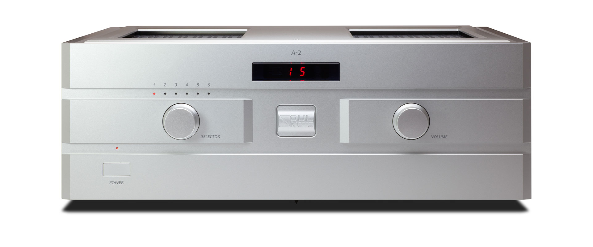
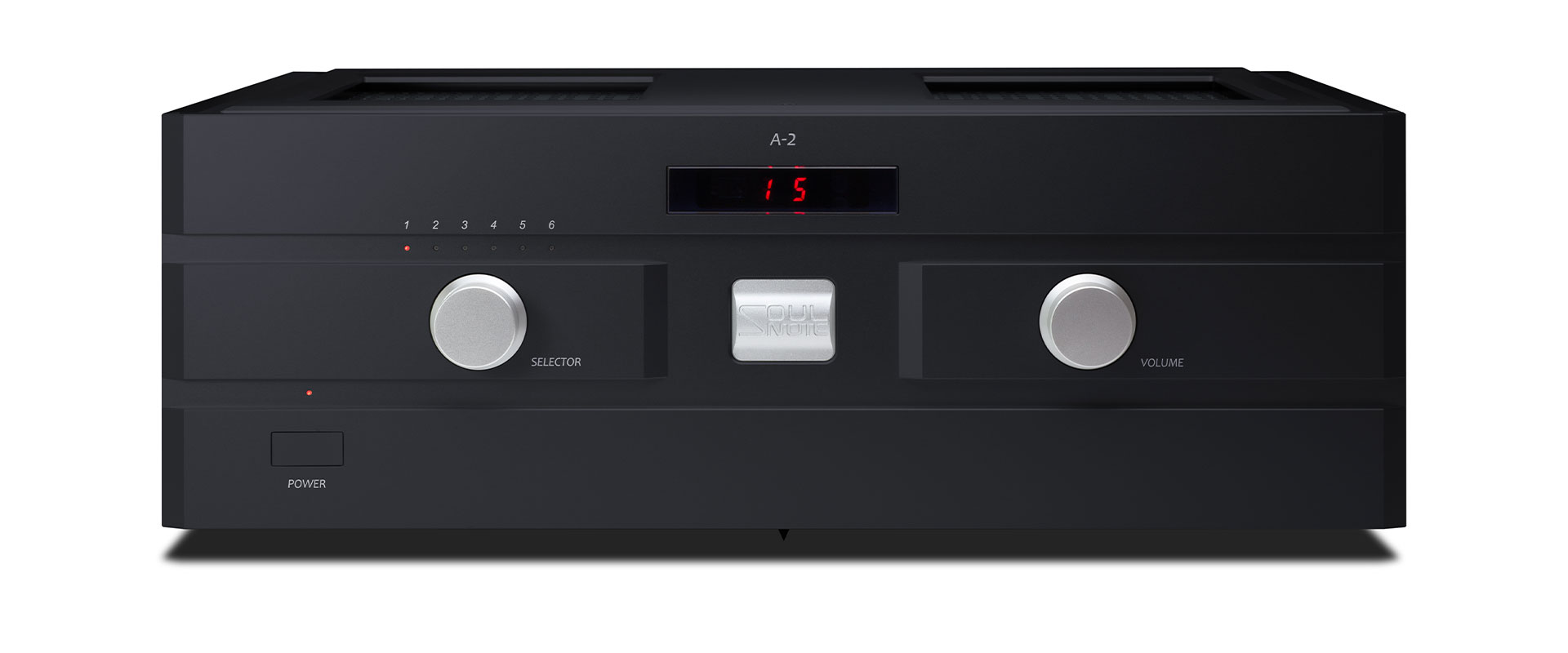
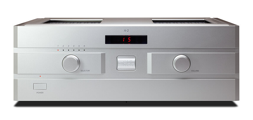
SOULNOTE A-2 ver.2
INTEGRATED AMPLIFIER Silver / Black
TECHNOLOGY
Simple configuration featuring a fully non-NFB Discrete circuit
The amplifier circuit employs a completely non-NFB design without feedback loop of any kind.
Its structure is deliberately simple — essentially a power amplifier equipped only with a selector and volume control.
This approach is essential to prevent any degradation of the audio signal and to preserve its absolute freshness and purity.
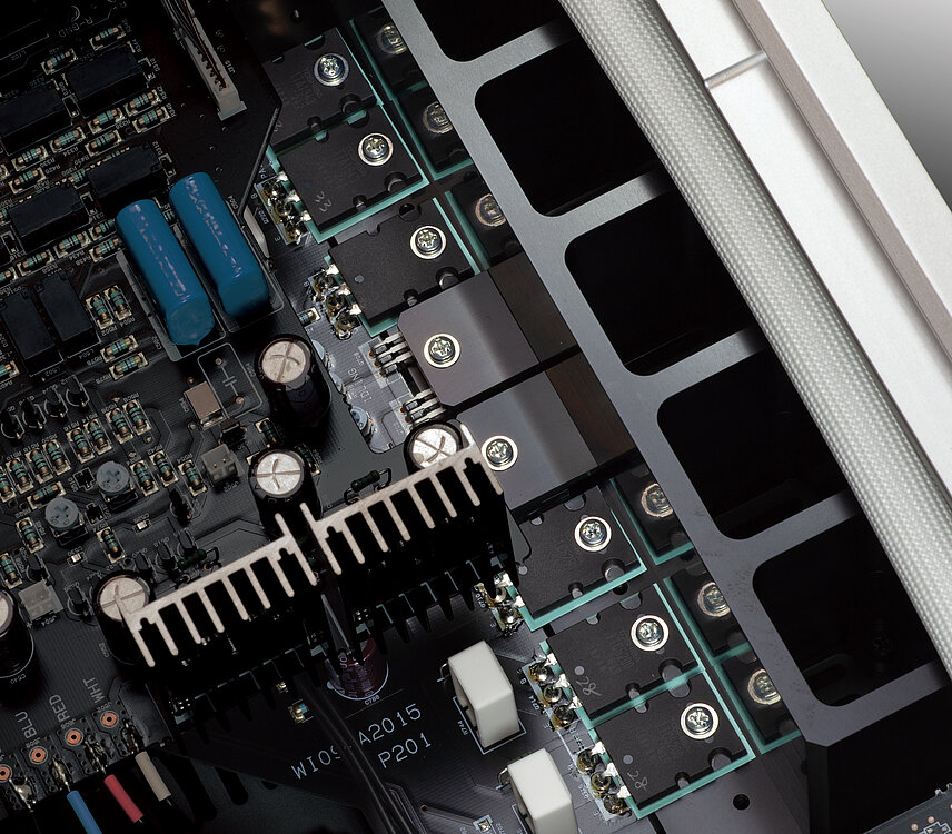
Parallel push-pull configuration using high-speed, high-power TO-3P transistors
The output stage employs the same parallel push-pull topology using high-speed, high-power TO-3P transistors as used in SOULNOTE’s flagship integrated amplifier A-3.
The output transistors are precisely paired based on their hFE characteristics, effectively eliminating the tonal smearing that can occur in conventional parallel push-pull designs.
Ultra-Powerful Driver Stage
The driver stage also employs the same TO-3P transistors used in the output stage.
The major difference from the original design is that a large standing current is applied to the driver stage.
By doing so, it instantly compensates for hFE variations in the output stage caused by current fluctuations, generating exceptionally strong driving capability. This advancement represents a true breakthrough in the circuit design.
Four-Stage Darlington Circuit
To fully drive the final output transistors, a four-stage Darlington configuration using high-frequency transistors is employed. The current levels in each stage are carefully optimized.
This design provides ample driving capability, delivering control over any loudspeaker.
Newly Developed Voltage Amplification Stage
The voltage amplification stage has been newly developed.
It has been significantly simplified, and the bias circuit has also been completely refined.
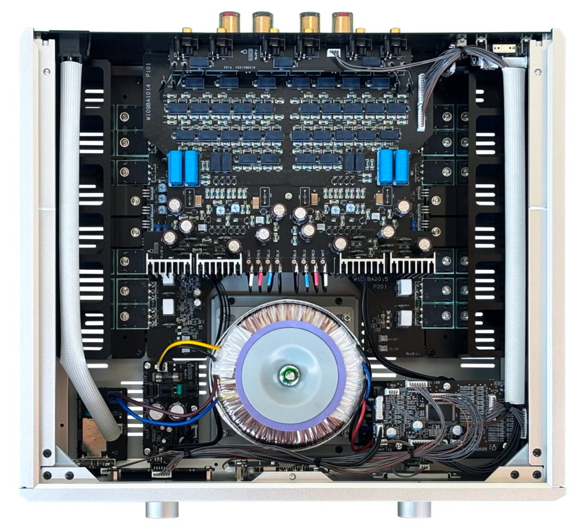
Non-Impregnated Large Toroidal Power Transformer
The output voltage has been intentionally lowered.
By doing so, priority is given not to maximum output at 8 Ω, but to the ability to deliver instantaneous current under low-impedance loads. This enhances perceived power and grip, resulting in far more powerfulness and grip.
Relay-switched Balanced Attenuator
The volume adjustment employs SOULNOTE's original relay-based attenuator system, which switches high-precision resistors in a balanced configuration. Transparency is dramatically enhanced, allowing the soundstage to emerge with three-dimensional clarity. It also is significantly improved quality in a low volume level without concern for gang error.
The ideal construction
The input terminals, input selector, volume control, and non-feedback voltage amplification stage are all concentrated onto a single multi-layer board. This minimizes the input signal path. Factors contributing to sound quality degradation, such as vibration in connecting cables, inductance components, and the effects of radiated noise, have been eliminated without employing any shielding or filters that could negatively affect the sound. This construction was only achievable through the relay-switching balanced attenuator.
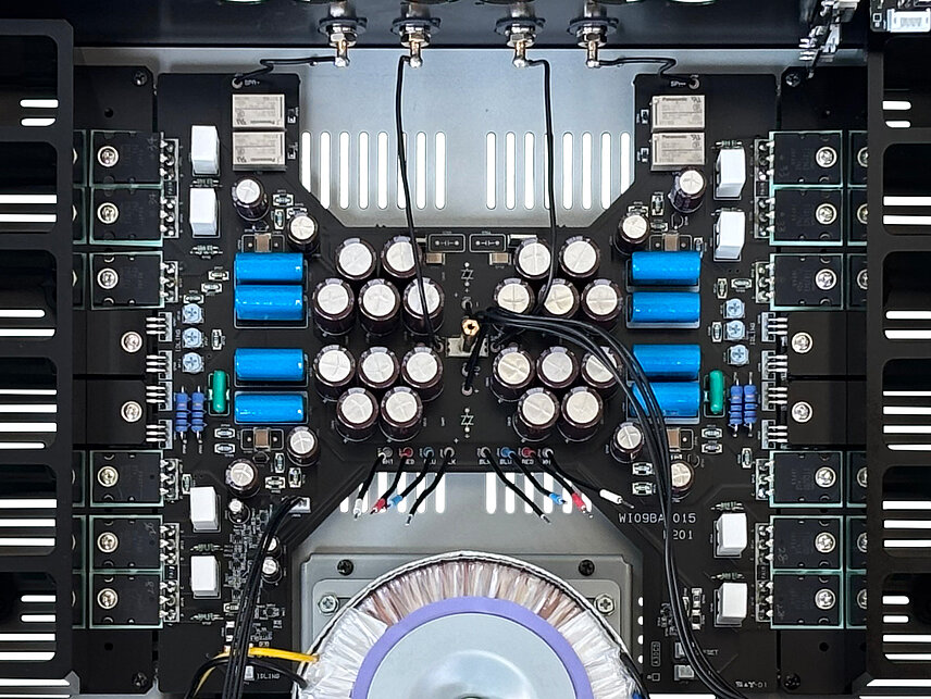
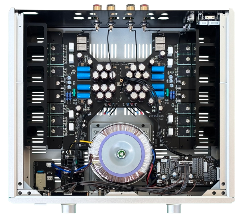
Four-layer board with 70-micron copper foil thickness
Composed of the output stage and the main power supply, the power block features an inner layer of 70-micron thick copper foil substrate inner layer plane as the power supply busbar.
The high-current loop – “rectifier capacitor → output transistor → loudspeaker plus terminals → loudspeaker minus terminals → rectifier capacitor “– is minimized. Eliminating inductance components in the high-current lines creates exceptional frequency response and stability.
Direct wiring without connectors
Connectors have been eliminated in the power supply as well as the signal lines, and cables are instead soldered directly to the boards for direct connections.
Chimney-type heat sink
The heat sink is applied chimney type that pursues a shape with high cooling efficiency and low intrinsic vibration.
Structure for highest sound quality
The entire structure is designed with sound quality as the priority. This includes the floating top cover and unsecured circuit board. Furthermore, the foot positioned directly beneath the power transformer serves to release its vibrations.
Power amplifier mode
This mode interrupts the power supply to the microcomputer and bypasses the selector and volume. This increases the S/N. XLR and RCA inputs can also be selected in this mode.
Four different selectable modes
The following four usage options are available.
Stereo integrated amplifier
Bi-amp monaural integrated amplifier
Stereo power amplifier
Bi-amp monaural power amplifier
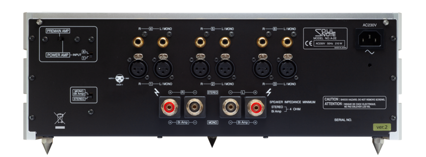
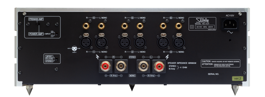
Rear panel
SPECIFICATIONS
| Maximum Output | 80W × 2 (8 Ω), 160W × 2 (4 Ω) |
| Total Harmonic Distortion | 0.16% (1 W / 8 Ω) |
| Frequency Response | Loudspeaker (8 Ω, 1W): 3 Hz to 240 kHz (±1.0 dB) |
| Input Sensitivity / Impedance | LINE 1, 2, 3 (BALANCED): 700 mV / 16 kΩ, LINE 4, 5, 6: 700 mV / 8 kΩ |
| S/N | 110 dB (IHF A network) |
| Power Voltage | 230V AC 50Hz / 115V AC 60Hz |
| Power Consumption | 210W, 70W (idling) / 235W, 70W (idling) |
| Dimensions | 430(W) × 162(H) × 423(D) mm |
| Weight | Approximately 20.0kg |
| Included Accessories | Remote control, Spikes, Power cable |